
A study on the design and implementation challenges of an aircraft hangar at Shah Amanat International Airport, Chittagong, Bangladesh.

Abstract
1. INTRODUCTION
The need for industrial steel buildings, especially pre-engineered steel structures, is increasing rapidly over time in several sectors [1]. Steel is a major construction material in civil engineering and is generally preferred over concrete [2]. Steel offers several advantages over concrete. Steel provides more structural strength, enabling vast open floor space for high efficiency in operation, can be built in much less time than reinforced concrete structures, has a longer lifespan and can be reused [3]. These advantages have led to a significant increase in the usage of steel structures in industrial warehouses, storage units, pedestrian bridges, workshops, commercial buildings, aviation hangars, manufacturing and assembly facilities, etc. [4].
However, challenges arise in the design and implementation of such structures based on the specific demands of the project and geographical limitations [5]. Achieving a design that is optimized for structural integrity while also being cost-efficient can sometimes prove to be difficult [6]. Steel components and elements must be designed in a manner that allows for transport to the construction site, as well as be compatible with existing technologies for implementation.
This paper focuses on such challenges encountered in the design and implementation phase of an aircraft hangar as well as their solutions. Aircraft hangars differ significantly from conventional buildings due to their requirement for large unobstructed spaces that facilitate aircraft movement and maintenance operations. In this project, the primary constraint during the design phase was maintaining a particular clear height with a defined maximum ridge height. A specific, clear height was essential to accommodate the entry of aircraft into the hangar. Additionally, the shear force in the primary design was substantially higher compared to the column capacity. In the implementation stage, the heavy-duty nature of the structure made it difficult to achieve proper weld penetration while maintaining structural integrity. Another challenge was the safe transportation and handling of heavy L-shaped columns, which could not be accomplished with the use of conventional trucks. The most critical part of implementation was the installation of the prefabricated members while preventing any sagging of the rafters or lateral movement of the columns. Addressing these issues demanded attention to detail and caution in engineering planning at both the design stage and the implementation stage. Therefore, this study may serve as a framework for the design and implementation of future projects of a similar nature.
2. PROJECT OVERVIEW
The project has been undertaken with the aim of constructing an aviation facility for CASA-235 aircraft. The free span of the hangar shed is 55.4580 m. There are two adjoining steel buildings of 7.8650 m width on both sides of the shed. The hangar shed consists of ten frames in total, which adds up to the total length of 52.2120 m. Fig. 1 presents the plan view of the project.

Fig. 1 General plan of the shed and office buildings
The ridge height of the hanger shed is 9.83 m, and the eave height is 7.24 m. Fig. 2 and Fig. 3 show the elevation view of typical sections of the project.

Fig. 2 Elevation of frame A and frame B

Fig. 3 Elevation of frame D to frame I
Each frame consists of a solid-web portal frame system except for the first two frames. The first two frames of the hangar shed utilize a combination of truss-rafter portal frame system. All the frames are supported by one steel column on each side. The end frame is supported by eight additional steel columns. The adjoining steel buildings has an equal number of frames with two decking floors.
The project site is in Chittagong, Bangladesh, which is a coastal region. Fig. 4 illustrates the actual status of this project after successful completion.

Fig. 4 Aircraft hangar shed after completion
3. DESIGN CODES AND ASSUMPTIONS
The design of this aircraft hangar shed adheres to several design codes, as represented in Table 1. Assumptions were made as per the instructions of the codes for pre-engineered steel structures.
Table 1: Codes used in design
|
Area of application |
Code name |
|
Design and analysis code |
AISC LRFD 2001 |
|
Wind load |
BNBC 2006 |
|
Seismic code |
UBC 94 |
|
Design load |
BNBC 2006 |
|
Purlin design |
AISI-LRFD 96 |
4. FABRICATION MATERIALS
The strength and specifications for materials used for the fabrication of structural elements are presented in Table 2.
Table 2 Specification of materials
|
Structural Components |
Specifications |
Strength (psi) |
Grade |
|
Built-up Column & Beam section (I section) |
ASTM A572 |
Fy = 50,000 |
50 |
|
Built-up Rafter section (I section) |
ASTM A572 |
Fy = 50,000 |
50 |
|
C section G.I purlin |
ASTM A653 |
Fy = 50,000 |
50 |
|
0.50mm Zinc Alum Color Sheet. Origin: Sysco, Taiwan |
ASTM A792 GR 550 MPa, AZ150 gm/m² |
Fy = 80,000 |
80 |
|
M.S Angle, M.S Pipe, MS Box |
ASTM A36 |
Fy = 36,000 |
36 |
|
Connection bolt |
DIN 933, Grade 8.8 |
Fu = 800 MPa |
8.8 |
|
MS Anchor bolt |
ASTM F1554 |
Fy = 36,000 |
36 |
|
0.70 mm thick decking sheet |
ASTM A653 |
Fy = 50,000 |
50 |
5. DESIGN PROCESS AND PRINCIPLES
STAAD.PRO v.8i software has been used to design and analyze the frame components of this aircraft hangar shed. First, the model was drawn with appropriate dimensions. Next, various loads were assigned to the frames. After that analysis of the completed model was conducted. Verification for errors, modification of member properties, and reiteration of analysis were done until the requisite level of accuracy and structural integrity was attained. Fig. 5 shows the 3D model of the shed in STAAD.PRO.

Fig. 5 STAAD.PRO model for aircraft hangar shed
6. DESIGN PHASE
The maximum height of the hanger shed needed to be kept under 9.7536 m. This restriction was imposed on the shed, designated for construction at an airport, to ensure clear passage for the transmission of navigational and radar signals. Additionally, this requirement sets a limit on the usable clear height for the aircraft. This limitation is because the hangar shed needed to have a lengthy free span. To attain this lengthy free span, it was necessary to utilise heavier sections, which led to significant deflection of the rafter members due to their own weight. In order to maximize the clear height within the imposed limitation, a technique named ‘camber’ was adopted in the design of the rafters. The application of cambering allowed the model's design to have an additional 76.4 mm ridge height instead of being restricted to 9.7536 m. Consequently, the maximum clear height is utilized while accounting for the deflection induced by the gravity load. The extra 76.4 mm also facilitated the implementation of a steeper slope for improved drainage and guaranteed the absence of ponding on the roof due to deflection. Fig. 6 and Fig. 7 show the value of dead load and roof live load acting on frame C. Fig. 8 and Fig. 9 illustrate the deflected shape of frame C resulting from dead load and gravity load, respectively, at the ridge. Table 1 represents the maximum deflection at the ridge resulting from these loads.
|
Fig. 6 Dead load acting on frame C |
Fig. 7 Roof live load acting on frame C |
|
Fig. 8 Vertical deflection due to dead load on frame C |
Fig. 9 Vertical deflection due to gravity load on frame C |
|
Fig. 10 Bending moment at frame B |
Fig. 11 Bending moment at frame C |
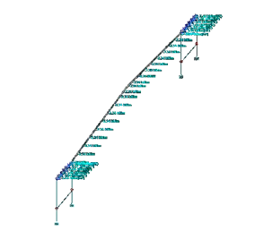





Table 3 Deflection due to dead load, roof live load and gravity load
|
Load |
Maximum Vertical Deflection (mm) |
|
Dead Load |
51 |
|
Roof Live Load |
30 |
|
Gravity Load |
82 |
Although the front section of the aircraft can be positioned easily inside the hangar, the aircraft’s empennage posed an additional challenge. The tapered I-section utilized around the ridge has a web-depth of 1500–1800 mm. Thus, the clear height at that region of the shed becomes 7.87 m. However, an extra 1.11 m of clearance was required to accommodate the aircraft's empennage. To resolve this issue, the depth of the rafter web was reduced to 697 mm. A hinge connection was incorporated at the ridge to ensure that no moment is generated since the decreased depth diminishes the load-bearing capacity of the rafter section. In the first two frames, a truss system was integrated with the I-section to compensate for the reduced depth of the rafter. These two frames were interconnected using a truss system to operate as a unified system. Hence, the first two frames were able to accommodate the design loads without exceeding the allowable deflection or experiencing failure. For the same reason as above, an additional 10 mm of thickness was added to the flange thickness of supporting columns in these frames. design considerations ensured structural integrity while providing an additional 177.8 mm of unobstructed room for the aircraft’s empennage inside the hangar. Fig. 10 and Fig. 11 illustrate that the inclusion of a hinge in the initial two frames makes the moment at the ridge zero, whereas the moment progressively increases toward the support, in contrast to the other frames. Fig. 12 shows an actual condition of the shed when aircraft enter the hangar shed.

Fig. 12 Aircraft inside the hangar shed during operational stage
The next major challenge during the design process was addressing inadequate shear capacity. The loads imposed on the structure produced a shear force substantially higher than the structure's capacity to withstand shear without failure. The inadequate shear capacity resulted in structural instability of the initial model. To resolve this issue, certain adjustments were implemented in the design of this aircraft hangar.
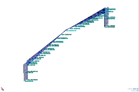
The first step involved modifying the layout of two office complexes within the aircraft hangar shed. The two-story office buildings on both sides of the shed were primarily positioned inside of the shed. In order to enhance shear capacity, the office buildings were now connected with the external section of the hanger shed. This integrated system exhibited a significantly greater moment of inertia compared to the previous design. The increase in the moment of inertia enabled the structure to withstand significantly higher lateral forces. Both offices building greatly affect the structural integrity of the model. Fig. 13 shows the amount of shear force generated in the Y direction in the model. Fig. 14 represents the same comparison for shear force in the Z direction.
|
Fig. 13 Shear force acting in Y direction on frame C |
Fig. 14 Shear force acting in Z direction on frame C |

The next step was the incorporation of shear keys into the base plates of the steel columns supporting the hangar shed. The anchor bolt's capacity in the base plate design was insufficient to withstand the applied shear force. The H-shaped shear keys provided with additional surface area to effectively transfer shear from the steel column base to the foundation and subsequently into the surrounding ground. Fig. 15 and Fig. 16 show the configuration of baseplate design incorporating both anchor bolts and shear keys.

Fig. 15 Detail of anchor bolt (AB – 1)
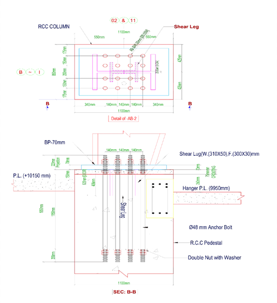
Fig. 16 Detail of anchor bolt (AB – 2)

Fig. 17 Anchor bolt layout plan
Fig. 17 shows the anchor bolt layout plan of the project. These two design changes greatly enhanced the hanger shed’s structural integrity and resistance to lateral forces.
7. IMPLEMENTATION PHASE
Upon the completion of the structural design, the first challenge encountered was the precise fabrication of the designed members. The fabrication process involved the production of large built-up sections using MS plates with a thickness between 25 and 50 mm. The joining of thick plates required proper weld penetration across the full thickness of the plates. To ensure full penetration butt welding of thick plates, multiple-pass welding procedures were adopted under strict quality control measures. Furthermore, accuracy of the whole fabrication process was ensured by conducting a full-scale mock-up assembly of the primary rafters and columns at the factory. Thus, the possibility of any problem regarding alignment, structural geometry, welding distortion, or joint fit-up was eliminated.
Following the successful fabrication of all designed components, the next issue was the safe conveyance of these prefabricated steel elements to the construction site. The columns of the hangar shed had an atypical L-shape, each weighing around 9 tons. Specialized trailers were employed for providing safe transportation due to the unconventional design, rendering conventional trucks unfeasible. Transportation was conducted during low-traffic hours. Upon arrival at the project site, all the structural members were unloaded using 50-ton and 25-ton mobile cranes in accordance with approved lifting plans and safety regulations.
The most critical problem emerged thereafter during the erection stage. The construction of a large clear span without internal supports could easily cause the rafter members to sag or the column sections to deflect. Since the construction site was coastal, substantial wind load also contributed to the associated risks. To resolve this problem, the two-story office buildings were erected first, followed by the commencement of the primary hangar’s construction. Fig. 18 shows the installation of L-shaped columns after the erection of office buildings. An outward offset of approximately 8 mm was provided at the columns to compensate for the anticipated deflection under the self-weight of the rafter. Fig. 19 shows the connection process of rafters with L-shaped columns.
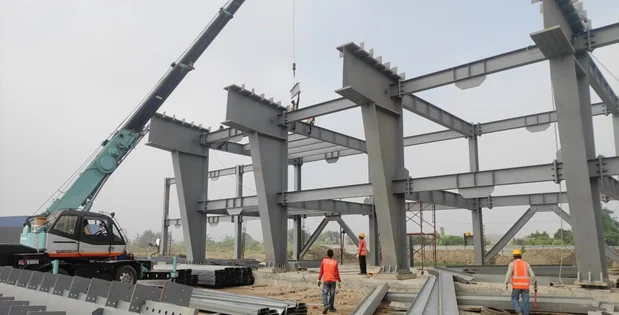
Fig. 18 Erection of office buildings and L-shaped columns of the shed
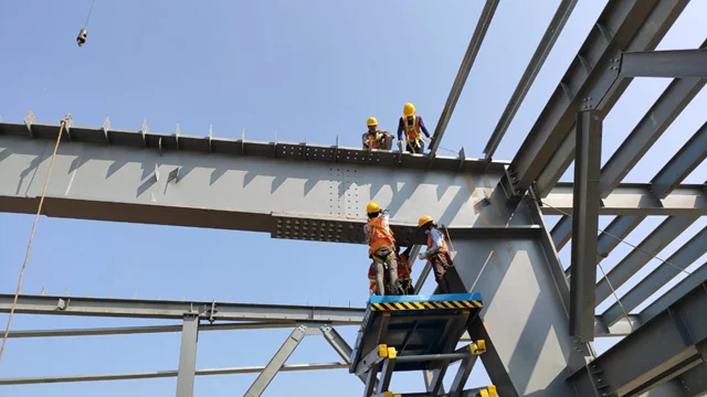
Fig. 19 Installation of the connection between the rafter and the L-shaped column
To safely perform the lifting operation, a total of five cranes were employed: one 100-ton crane at the center, two 50-ton cranes at both sides, one 25-ton crane, and one 12-ton crane, which is shown in Fig. 20.

Fig. 20 Cranes used in lifting operation
To prevent sagging during erection, seven temporary I-section supports were placed beneath each rafter and retained until the permanent bracing and purlin systems were completed. After the structural system was fully completed, all temporary supports were systematically removed following technical confirmation of structural stability. Thus, the erection process was successfully completed.
8. RESULTS AND DISCUSSIONS
The design and implementation of the aircraft hangar project was done successfully within the approved duration while maintaining the required quality standards. The hangar shed would provide adequate space for aircraft maintenance and long-term structural stability. Table 4 represents a summary of maximum shear force, bending moment, and displacement encountered in the final design of the hangar shed. Table 5 shows the estimated quantity of steel that was required for the successful implementation of the designed shed.
Table 4: Summary of software analysis
|
Direction |
Maximum displacement (mm) |
Maximum shear force (KN) |
Maximum bending moment (KN-m) |
|
X – axis |
-11 |
-3641 |
-93 |
|
Y – axis |
-82 |
-1842 |
-978 |
|
Z - axis |
449 |
674 |
1231 |
Table 5: Summary of the required steel quantity in MT
|
Supplied Items |
Quantity |
|
Build up I section Column, rafter, Beam, Sub-beam, Box Bracing, Base Plate |
1,340 |
|
Galvanized nut bolt with washer. |
34 |
|
Purlin & Grit |
52 |
|
Stress bar & sag rod |
4 |
|
0.47 mm thick zinc alum profile sheet for Roof and wall sheeting |
21 |
|
Anchor Bolt |
11 |
|
0.70mm mm thick Galvanized Decking Sheet |
26 |
|
Total Quantity of Steel Obtained |
1,488 |
9. CONCLUSION
The design and analysis in this study efficiently address unique challenges such as allocation for aircraft clearance requirements, compliance with shed height restrictions, and structural issues associated with a large span. In addition, the study represents solutions regarding the successful implementation of the project. This project is a significant accomplishment in the domain of steel structure construction in Bangladesh. The successful execution of the project was ensured by innovative design solutions, meticulous planning, quality control, and safety management.
REFERENCES
[1] Titiksh, A., Dewangan, A., Khandelwal, A., & Sharma, A. (2015). Comparative study of conventional steel building and pre-engineered building to be used as an industrial shed. International Journal of Engineering Research and Applications, 5(11).
[2] El-Reedy, M. A. (2010). Construction management and design of industrial concrete and steel structures. CRC Press.
[3] Brynhildsen, H. (2020). Advantages of steel as a building material from a sustainability perspective.
[4] NDEMEFO ATEFACK, E. M. M. A. N. U. E. L. (2021). Analysis and verification of the behavior of industrial steel structures with and without bridge cranes. Case study: Zin industries’ factory at Mvan Yaoundé.
[5] Ballio, G., & Mazzolani, F. M. (1983). Theory and design of steel structures. Taylor & Francis.
[6] Faisal, M. M., & Das, P. C. (2022). Fabrication-Driven Structural Optimization Techniques for Cost-Efficient Steel Construction Using CNC-Based Design Workflows. American Journal of Interdisciplinary Studies, 3(04), 464-499.
Comments 0
No comments yet. Be the first to comment!
Sign in to leave a comment.